Summary
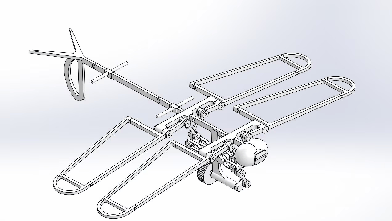
This project began as a way to explore the combination of a quadcopter and a fixed-wing aircraft: a dragonfly-inspired microglider. The aim was to see if the agility of an ornithopter-like system could be paired with the efficiency of a glider, and to capture that interaction in a physics-based model. Modelling the system primarily as a tailless, tandem-wing aircraft, I was able to track its longitudinal aerodynamics and stability. Imitating dragonflies, I modeled a tiny mass sliding along the fuselage under a basic feedback loop, letting the glider self-correct its attitude. Once the model was behaving as expected, I used it to explore how stability and efficiency change across thousands of configurations, searching for those rare combinations that glide well but still hold steady in disturbances. The final mathematical model ultimately laid the groundwork for a hardware prototype that marries quadcopter-like maneuvering with fixed-wing-style endurance.
Aerodynamic Modelling
I began with a point-mass ODE model in MATLAB — lift and drag were both applied at a single point, and the angle of attack was taken to be equal to the flight-path angle. This stripped-down version was meant to verify the fundamentals first, rather than chase full realism right away. It reproduced classic phugoid oscillations, which was exactly the sort of “sanity check” I wanted before moving on.
From there, I expanded to a rigid-body model with pitch dynamics. Adding pitch angle and pitch rate meant each wing could see a non-zero local angle of attack, which made the system sensitive to configuration changes like wing incidence and CG location. Eventually, I transitioned this into a tailless tandem-wing model, where a small difference in incidence angles between the two wings could theoretically balance the aircraft in steady glide. At this point, the model had enough fidelity to begin exploring how subtle geometry changes affected real flight behaviour.
\[\begin{array}{cc} \dot V = -\frac{D}{m} - g\,\sin\gamma \qquad & \dot \gamma = \frac{L}{m\,V} - \frac{g\,\cos\gamma}{V} \\\\ \dot \theta = q \qquad & \dot q = \frac{M_{tot}}{I_{yy}} \end{array}\]There were still simplifications at this stage. I used flat-plate aerodynamics at each wing center, neglected any aerodynamic effects from the fuselage, and assumed the downwash from the front wing was constant. Moments of inertia were calculated using the parallel-axis theorem with all components modeled as point masses. While this left out many second-order effects, it kept the simulation fast enough to run large sweeps without losing the main aerodynamic trends.
Pitch Control with C.G. Variation
The idea was to generate pitching moments on demand without relying on servo-driven control surfaces. Looking at slow-motion dragonfly flight, dragonflies achieve this through pivots in their abdomen, effectively changing their C.G. I wanted to see if a similar mechanism could be replicated in a glider using only a moving internal mass.
To find the sweet spot, I swept the center of gravity (CG) by virtually moving a small weight along the fuselage. Each run produced different glide slopes and trim angles, and I kept meticulous notes on how small CG shifts translated to changes in flight behavior. It quickly became apparent that the optimal CG location — about 48 % of the fuselage length — balanced minimal sink rate with enough passive stability to avoid wild oscillations. From this sweet spot, a mass could be ramped up and down the fuselage to pitch the aircraft.
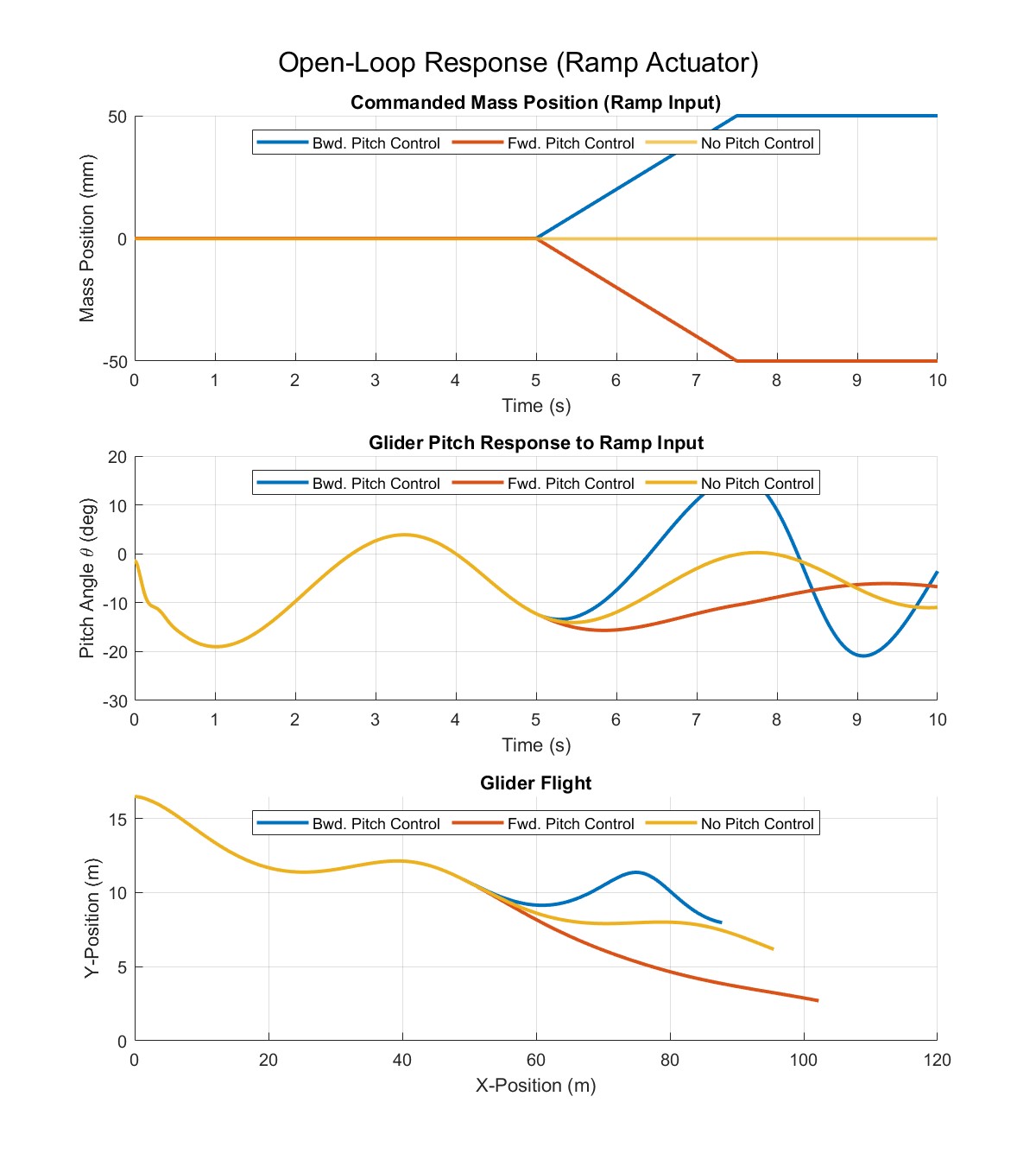
To emulate this, I coded a simple PID controller around the position of a 4 g mass, tuning the proportional, integral, and derivative gains through repeated trial runs. Initially, the controller either oscillated wildly or drove the mass to one extreme, so I introduced position limits and a small rate damper in the loop. By adjusting the integrator windup and testing against step changes in target trim angle, I landed on a configuration that settled to level flight in about ten seconds with just a hint of overshoot. Although the gains were only effective for small target flight angles, they still proved a strong example for a more robust future variant.
Static and Dynamic Stability Analyses
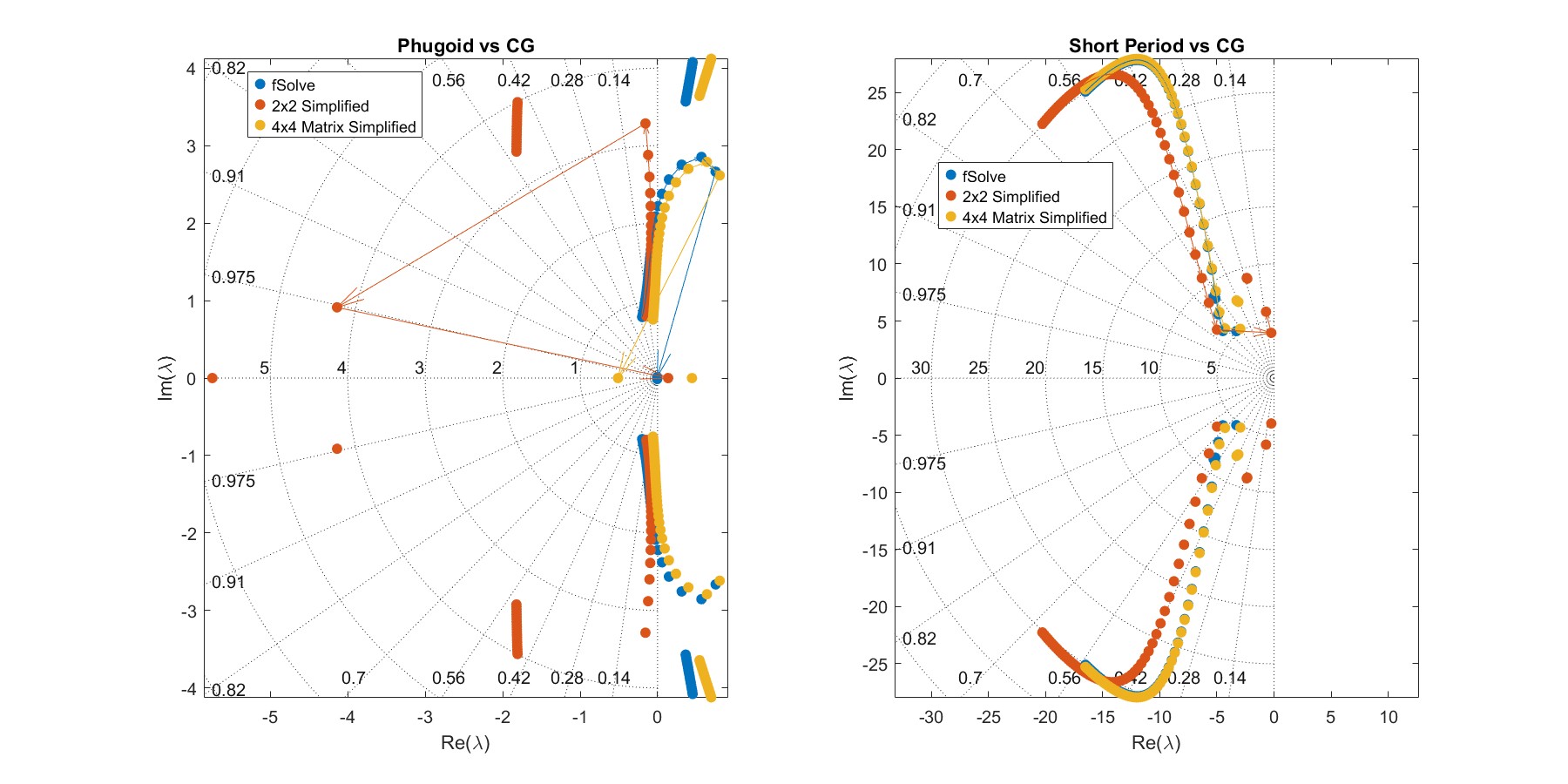
Once the control system was working, I shifted focus to mapping out the model’s stability limits in more detail. My goal wasn’t just to see if the glider was stable or unstable — I wanted to quantify exactly how each stability mode changed with geometry and flight condition. I approached this in three different ways. The first method used MATLAB’s fsolve to directly find trimmed equilibrium points, solving for a steady velocity and angle of attack at each CG position and speed. The second method was more old-fashioned: I pulled a simplified, decoupled 2×2 formulation for the short-period and phugoid modes straight from a flight dynamics textbook. The third approach bridged the gap — I built a coupled 4×4 state-space system from the rigid-body equations. For each method, I then linearized the full nonlinear equations via finite-difference Jacobians, which gave me the eigenvalue mode decomposition. This let me compare how much accuracy each level of complexity was actually buying me.
Comparing the three approaches, the 4×4 model turned out to be the sweet spot. It ran far faster than the full fsolve plus Jacobian method, but the eigenvalues it produced were much closer to that “gold standard” than the decoupled 2×2 results. Across the two more advanced methods, the trends were consistent: as the CG moved aft, the short-period oscillation became more pronounced and less damped, and once it passed about 98.8 mm from the nose, the phugoid mode tipped into instability. That threshold became a clear “red line” for later design sweeps — cross it, and the model’s dynamics quickly became too unpredictable.
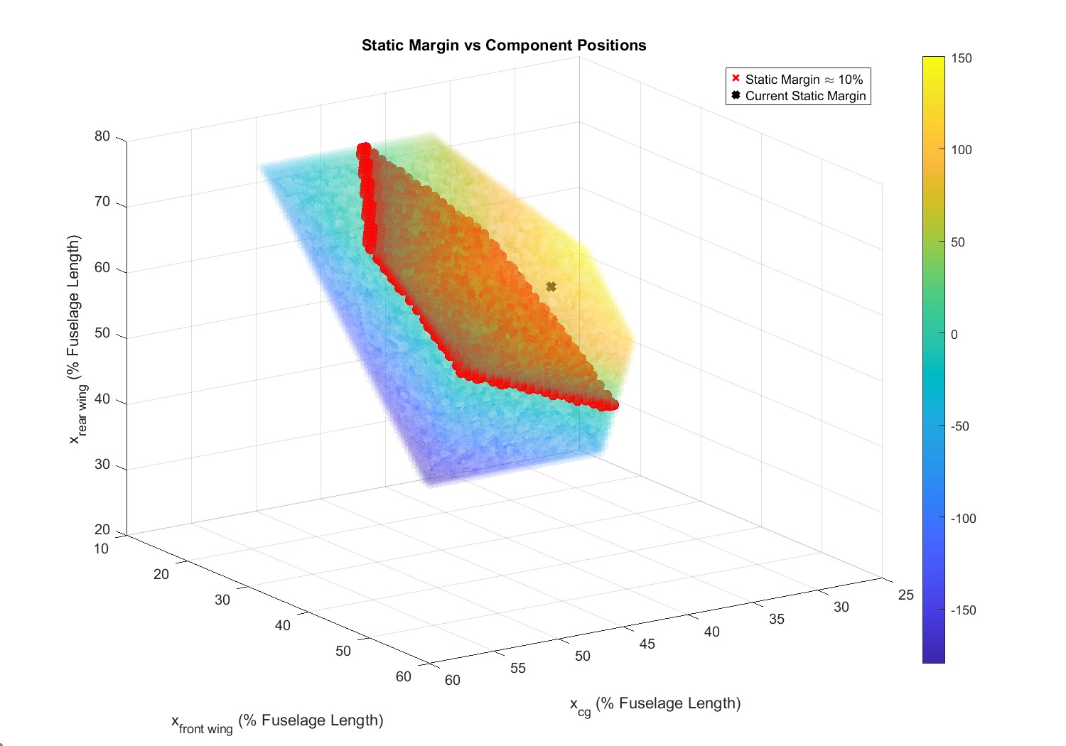
I also wanted to understand the static stability picture, so I computed the neutral point by solving for the angle of attack where the pitching-moment slope was zero. From that, I calculated the static margin as a quick metric for “how stable” a configuration was before even looking at dynamic modes. Most of the well-behaved configurations clustered in the 8–12 % static-margin range, which matched the textbook recommendation for a vehicle that isn’t overly sluggish but won’t twitch uncontrollably with small disturbances. The fact that both dynamic and static methods pointed to this same band was reassuring, and gave me more confidence in the model.
I also plotted the theoretical static margin of the current physical glider model. The prototype’s static margin was calculated at 60%, a value much higher than any flyable plane would have. This could have strongly suggested an error in my calculation; however, I could not find one. Because the physical glider had only been test-launched a few times and glided as expected, there was no verification that this calculation was necessarily wrong. If anything, it highlighted how far the real hardware could be from “ideal textbook numbers” and still function acceptably.
Design Space Exploration
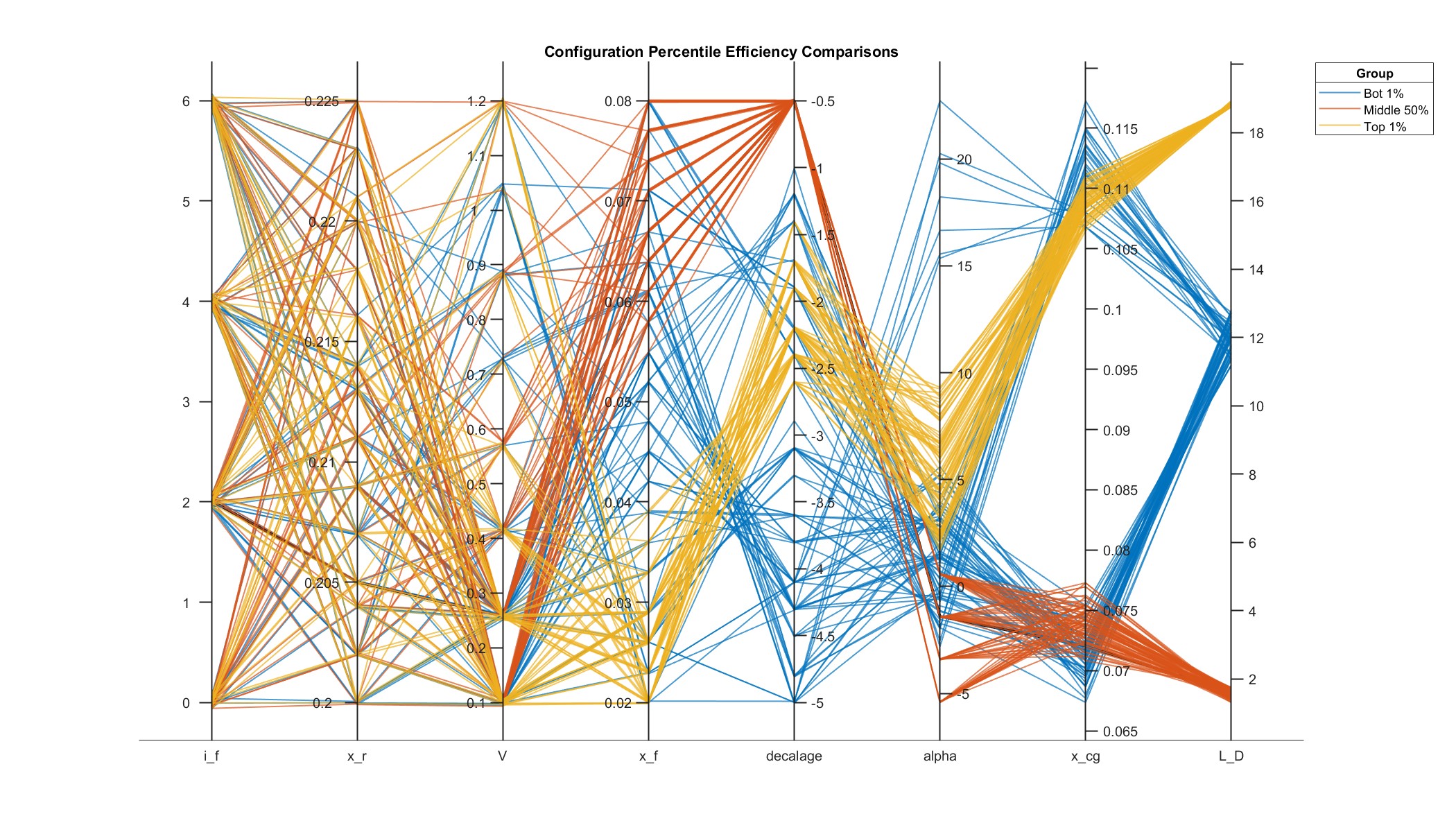
With insights on passive stability, active control, and aerodynamic performance, I set up a high-dimensional sweep over five variables: CG position, front wing incidence and distance, wing gap, and decalage angle. The script cranked through tens of thousands of combinations, automatically discarding any design that failed to trim or fell outside our target static-margin window.
From the list of viable designs, I isolated the top 1% by L/D and plotted them in a parallel-coordinates chart. That visualization revealed clear coupling trends: the best configurations all had a C.G. around 43% of the glider’s length, a decalage angle of -2.5\(^\circ\), and a forward-placed front wing. Conversely, the bottom 1% of designs had decalage angles approaching 0° and a C.G. at 20% of the fuselage. The comparison of these two extremes showed a similar final theme: the particular placement of the rear wing did not strongly affect L/D. These multi-variable patterns highlighted a key list of priorities, defining a “goal” for different designs to aim for if they seek high L/Ds.
This particular analysis also suggested the front-wing incidence was irrelevant; however, I realized this was an issue with the model itself. The wings were the only aerodynamic bodies simulated, so the fuselage — which would normally help keep a glider in near-level flight — did not contribute to any aerodynamic-based moments. Essentially, in-program, the model was effectively flying sideways like a biplane rather than a tandem-wing. It was a limitation worth noting, but the patterns from the sweep were still valuable in shaping the next iteration of the design.