Summary
An essential component of each competition cycle is to correctly identify the highest-scoring design space for our aircraft. An accurate and precise analysis allows the team to quickly transition from a broad idea to designing aircraft and mission-specific components. The goal of a all-encompasing sizing script is therefore to asses a wide range of possible plane configurations, dimensions, mission capacities and procedurally isolate the highest-scoring, viable option.
The process was broken into four essential parts: aerodynamics, mechanical structures, propulsion, and optimization. The purpose of the first three modules was to simulate the complete mission performance of an aircraft. This included mathematically identifying aerodynamic perfomance, intertia tensors, and electronic ability. With this information, the optimization module could simulate thousands of combinations, using a natural-selection-esque approach to “breed” the best plane.
Aerodynamics
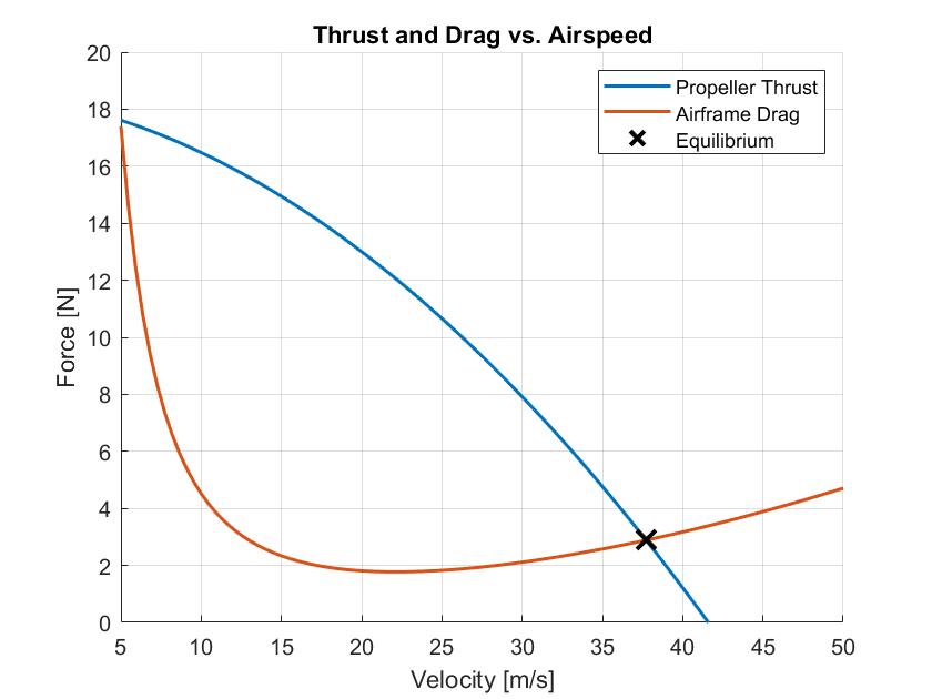
The aerodynamics module serves as the core flight dynamics simulator, translating the aircraft’s physical properties into a comprehensive performance and stability profile. Its primary purpose is to determine the aircraft’s mission lap time while verifying that the design is aerodynamically stable and viable across all required flight phases. This analysis begins by establishing the steady-state cruise condition through a critical equilibrium-seeking process.
This process iteratively solves for a flight velocity where the thrust generated by the propulsion system is precisely balanced by the aircraft’s total drag. Concurrently, the module calculates the pitching moments generated by the wing and horizontal stabilizer to ensure the aircraft is balanced. This dual-convergence loop determines the required angle of attack and elevator deflection for trimmed, level flight, establishing the fundamental lift and drag coefficients for the cruise phase.
\[\begin{array}{cc} M_{\text{total}} = L_W (x_{ac,W} - x_g) - L_H (x_{ac,H} - x_g) = 0 & & & & F_{\text{total}} = \underbrace{\frac{1}{2}\rho V^2 S C_{D,0}}_{\text{Parasite Drag}} + \underbrace{\frac{L_W^2}{\frac{1}{2}\rho V^2 \pi b_W^2} + \frac{L_H^2}{\frac{1}{2}\rho V^2 \pi b_H^2}}_{\text{Induced Drag (Wing + Tail)}} = 0 \end{array}\]To ensure high-fidelity results, all aerodynamic forces are derived from a pre-compiled database of airfoil performance data. The module selects the appropriate lift and drag characteristics for the wing and tail surfaces based on the calculated Reynolds number for the specific flight condition.
With the cruise state established, the module performs a rigorous stability analysis. First, it calculates the longitudinal static margin—the distance between the center of gravity and the neutral point—to ensure the aircraft has a natural tendency to return to its trim angle of attack. Following this, a full dynamic stability analysis is conducted by calculating the eigenvalues of the aircraft’s characteristic modes of motion. This includes the longitudinal modes (Phugoid and Short Period) and the lateral modes (Dutch Roll, Spiral, and Roll Subsidence). The real and imaginary components of these eigenvalues are checked to confirm that any oscillations are naturally damped and the aircraft is dynamically stable.
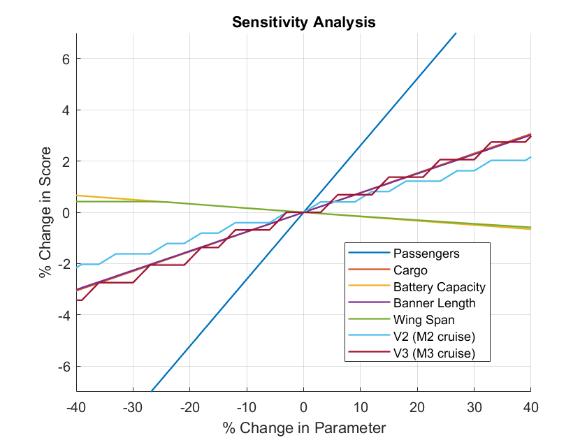
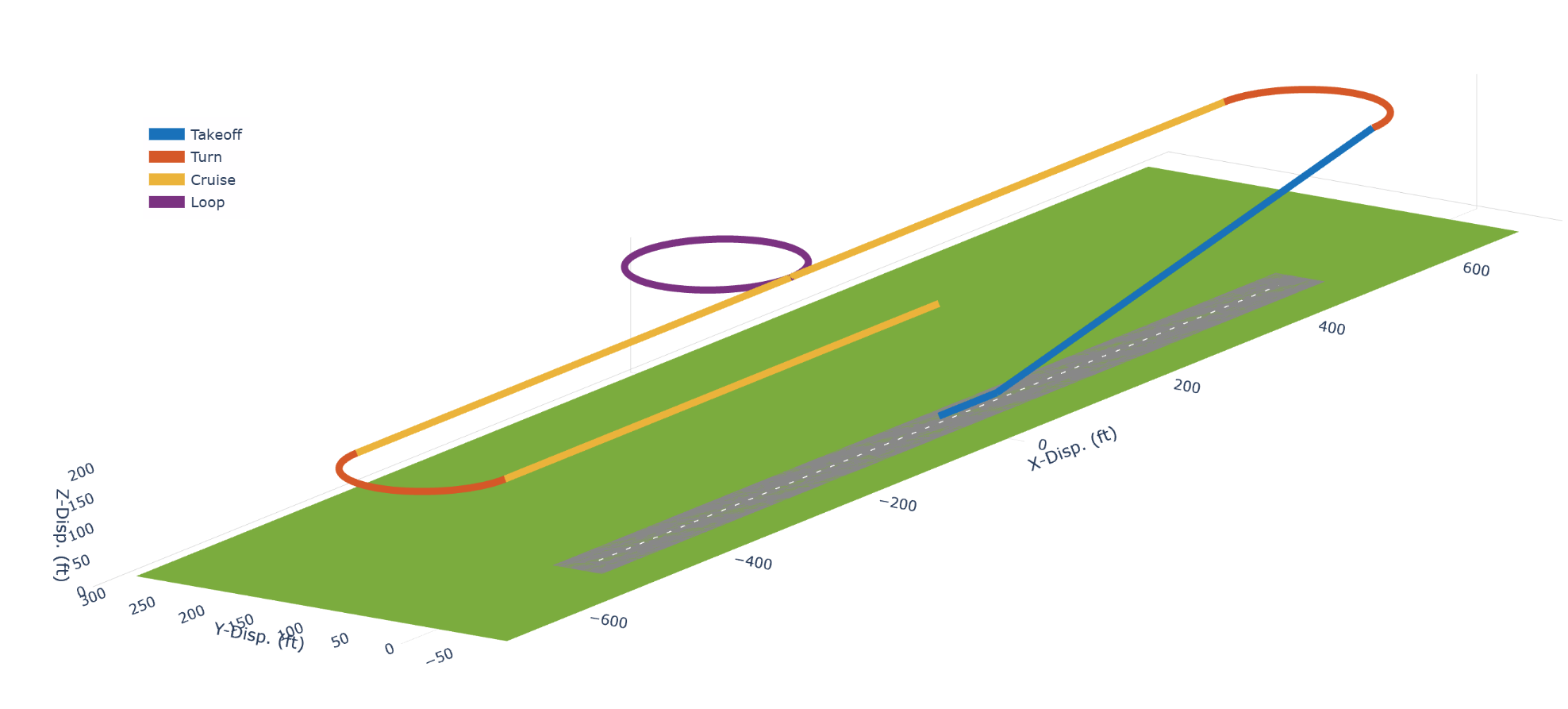
Finally, the module simulates the complete mission profile. It models the takeoff ground roll by integrating the forces of thrust, drag, and friction to calculate the takeoff distance. It also analyzes the aircraft’s maneuvering performance to determine the maximum sustainable turn rate. These distinct phases (takeoff, cruise, and turning—arc) combined to calculate a total mission lap time, which serves as the primary fitness score for the optimization algorithm.
Mechanical Structures
To accurately model the physical characteristics of any given aircraft design, the mechanical structures module employs a comprehensive, component-based approach. The primary objective is to calculate the aircraft’s total mass, the precise location of its center of mass (CM), and its complete inertia tensor. These values are fundamental inputs for the aerodynamics module, as they directly influence flight stability and performance.
The process involves a bottom-up summation of every major aircraft component, including the wing, tail assembly, fuselage, propulsion system, landing gear, and mission payloads. Each component’s mass and inertia are calculated based on its geometry and material properties, which are defined in the design vector. For instance, the mass of lifting surfaces like the wing and tail is determined by aggregating the mass of individual structural elements such as spars, ribs, and skin, accounting for the densities of materials like balsa, carbon fiber, and Monokote. The center of mass for an airfoil section is typically approximated to be at its quarter-chord point (25% of the chord length back from the leading edge). For a trapezoidal wing that has a straight, unswept leading edge, the taper from a wide root chord to a narrow tip chord causes the quarter-chord line to be swept backward. The angle of this sweep, \(\Lambda_{25\%}\), is calculated geometrically based on the wing’s aspect and taper ratio, \(\lambda\). The following formula was used:
\[\tan(\Lambda_{25\%}) = \frac{1}{4} \frac{AR(1 + \lambda)}{AR} \frac{c_{root} - c_{tip}}{b/2} = - \frac{1}{4} \frac{1 - \lambda}{AR(1 + \lambda)}\]To ensure accuracy in calculating the center of mass and rotational inertia for complex shapes, a strip integration method is applied to the wing and tail surfaces. This technique divides the surfaces into smaller, simpler segments, whose properties can be calculated and then summed. The inertia tensors of all individual components are first calculated relative to their own centers of mass and then translated to the aircraft’s main origin using the tensor version of the parallel-axis theorem, show below. By summing the mass and origin-referenced inertia of every part, the module produces a complete mass and inertia profile for the entire aircraft, which is then used to determine the final location of the combined CM and the aircraft’s inertia about that point.
\[\mathbf{I}_{\text{origin}} = \mathbf{I}_{\text{CM}} + m \left( (\mathbf{r} \cdot \mathbf{r})\mathbf{E} - \mathbf{r}\mathbf{r}^T \right)\]Ultimately, the mechanical structures module’s ouput contains a detailed breakdown for each mission. allows the optimization algorithm to realistically assess the physical viability and dynamic behavior of each design iteration.
Propulsion
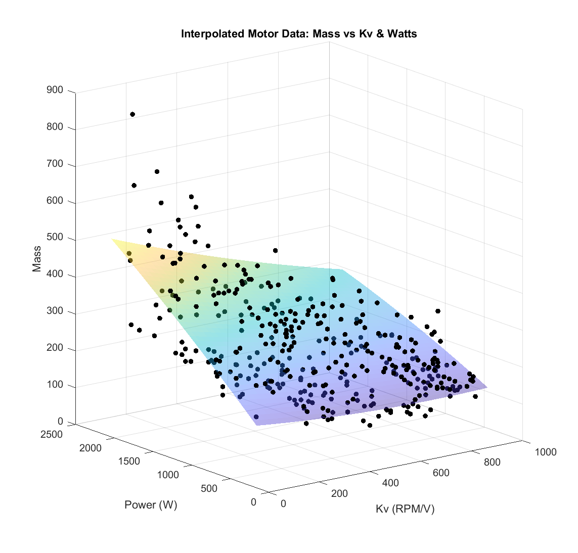
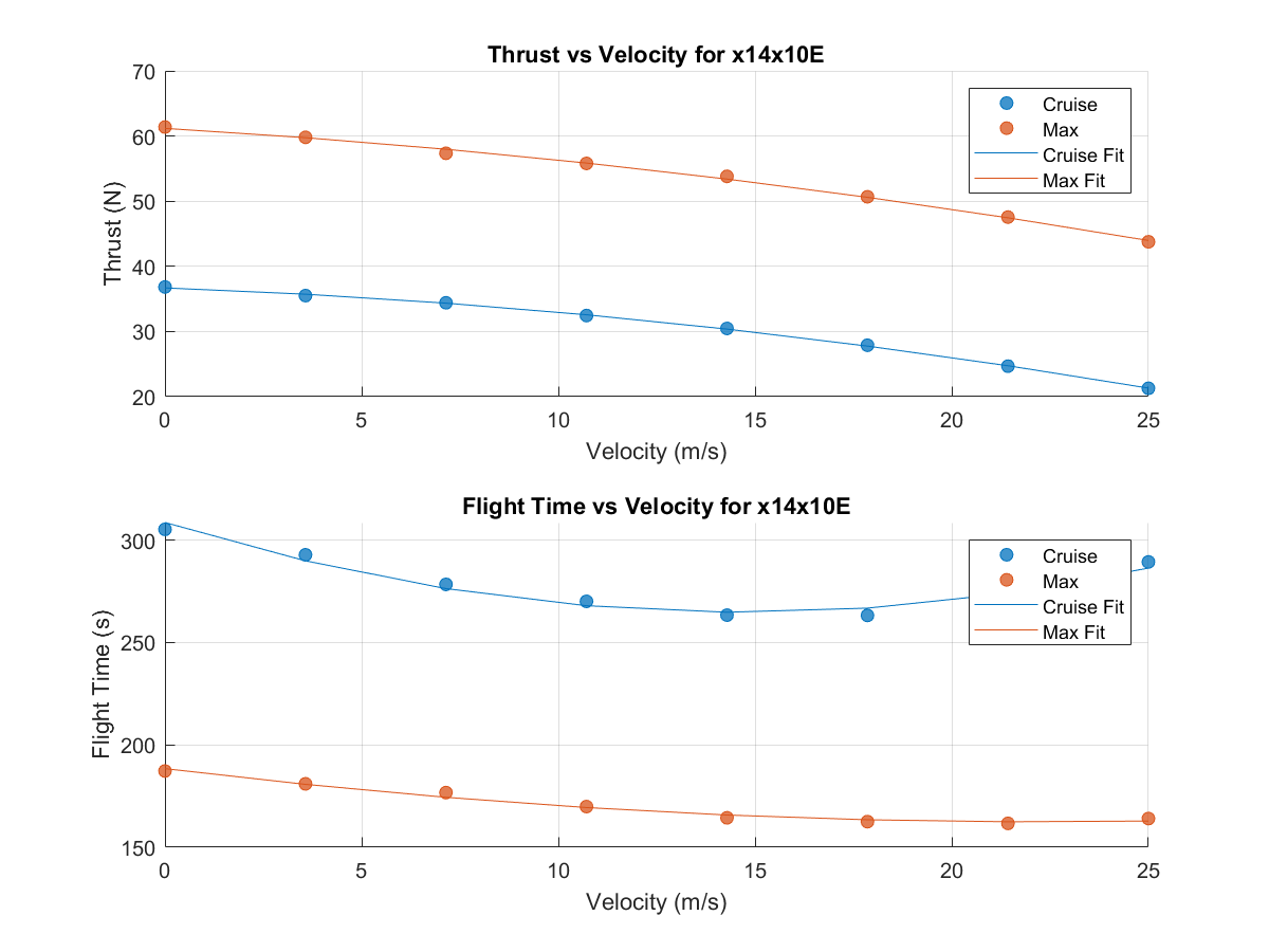
To guarantee hightest-fidelity results, the propulsion module utilized official performance simulation data from the manufacturer of propellers APC. Amongst other quantities, APC provided torque (Nm), thrust (N), and mechanical power (W) data for a wide range of propeller RPMs and incoming air velocities, \(V_{0}\). Using this information, it was possible to create an interpolation function: given a specific RPM and velocity, the function would output torque and thrust.
Given these values, in addition to motor and battery properties, the program could then evaluate the corresponding current pull, voltage sag, and EMF generated by the spinning motor. Next, there were a few edge-cases to consider. As RPM increases, eventually the current pull becomes too high for the motor, and it surpasses its maximum wattage rating. This kind of failure means the motor should not be used with the propeller at this RPM and \(V_{0}\). Throttle is also a concern - when the induced EMF reaches the battery’s sag voltage, the motor will not be able to increase its RPM. Consequently, for a given operating point, a throtttle can be determined with the equation below. These two cases largely establish the outer limits of the motor.
\[\text{Throttle} = \frac{V_{\text{EMF}}}{V_{\text{Sag}}} \times 100 \%\]For a set velocity, this outer-bound operating point was identified using a binary search algorithm. Starting with a set upperbound and lower bound for RPM, it would check if the middle RPM could pass a motor check. If the check was successful (throttle was under 100% and motor power was not at its max), this values was set as the new lowerbound. Honing in on the maximum possible RPM, this process was completed for a range of velocities and the curve-fit outputted to the Aerodynamics module. The final result was two curves: max thrust over \(V_{0}\) and flight time over \(V_{0}\).
Optimization
To effectively search the vast design space for the optimal aircraft configuration, an optimization module based on the principles of natural selection was developed. This genetic algorithm mimics the process of biological evolution, allowing generations of aircraft designs to “evolve” towards a higher-scoring solution. Each potential aircraft design is treated as an “individual” in a population, with its unique set of design parameters encoded into a binary string, analogous to a chromosome.
The optimization process begins with an initial population of randomly generated aircraft designs. Each of these designs is then evaluated using a “fitness function,” which calculates a score based on the simulated mission performance. This score quantifies how well a particular design meets the competition’s objectives.
Following the fitness evaluation, a process of “natural selection” occurs, where the higher-scoring “individuals” are more likely to be selected to “reproduce.” During reproduction, the binary “chromosomes” of two parent designs are combined through a process called crossover to create offspring. This allows for the exchange of design characteristics, potentially leading to even better solutions. To introduce further diversity and prevent premature convergence on a suboptimal design, a small degree of random mutation is introduced into the offspring’s genetic code.
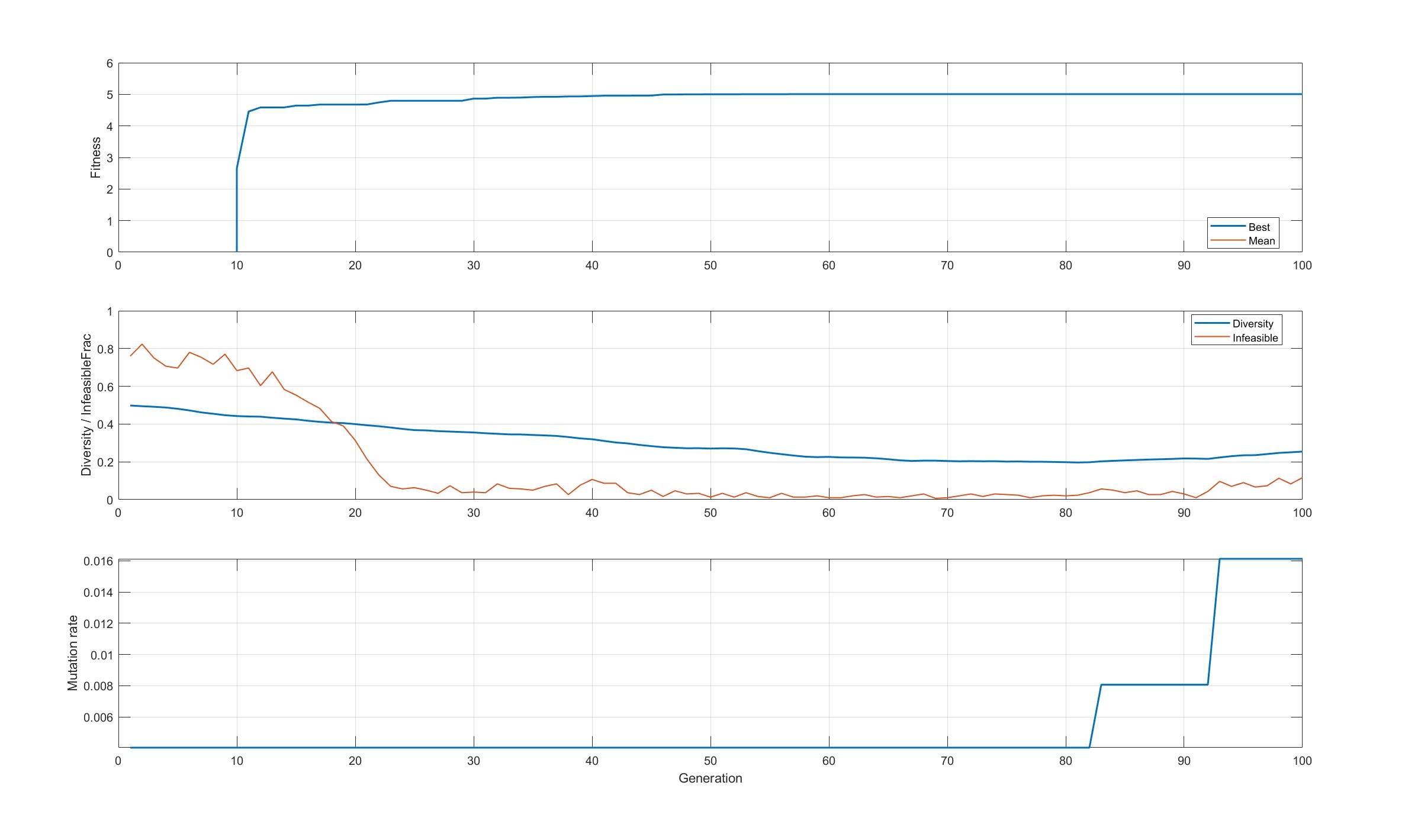
This cycle of evaluation, selection, crossover, and mutation is repeated for a set number of generations. Over time, the population of aircraft designs evolves, with the average fitness of the population generally increasing with each generation. Through this “survival of the fittest” approach, the algorithm systematically explores the design space and converges on the highest-scoring, viable aircraft configuration.