Summary
To better validate our propeller models, I built a custom thrust testing rig designed for modular use and sensor integration. Originally, we had a basic L-bracket system with a motor mount on one end and the other resting on an electronic scale — it worked well enough to estimate thrust at full throttle, but wasn’t ideal for fine-grained data collection. The new design prioritized Arduino-based motor control, sensor integration, and the ability to switch between static and dynamic testing. It ended up being a compact and robust system that gave us much more precise insight into motor and propeller behavior.
Refined Motor Control
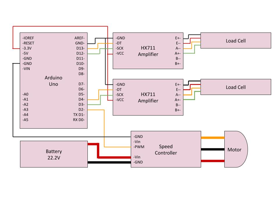
Before, motor control was handled manually using a standard RC transmitter and receiver. That setup worked, but didn’t give us access to the actual throttle signal — and it didn’t play nicely with automated data collection. So, I switched to controlling the motor directly through an Arduino, sending PWM signals to the ESC just like a transmitter would.
This change gave us two big benefits: I could now log and control throttle digitally, and I could program repeatable throttle sweeps for testing. One important realization during this process was that the motor didn’t start spinning until a certain minimum throttle — meaning there was a dead zone at the low end. To address this, I stepped through throttle values in 5% increments, holding each for five seconds to allow the motor to stabilize while the Arduino recorded thrust data.
This test sequence ran twice — once ramping throttle up, and again ramping it back down. Interestingly, I observed different behaviors in the motor response: on the way up, thrust plateaued around 80% throttle, but on the way down from 100% it decreased smoothly from that maximum. This behavior gave useful insights into motor dynamics that wouldn’t have been seen with manual control. Mo
Sensor Data
While the goal was to integrate a full suite of sensors — including current, voltage, RPM, and wake speed — those weren’t all ready in time for the first round of testing. I relied on visual readouts from commercial sensors for electrical measurements and focused on logging thrust and torque with load cells.
The load cells were calibrated extensively beforehand, and I was initially worried that vertical shear forces from gravity might throw off the readings. But after some analysis and testing, I found that the dominant forces from thrust, and torque were orders of magnitude larger than any gravitational side loads — most likely making the effect negligible.
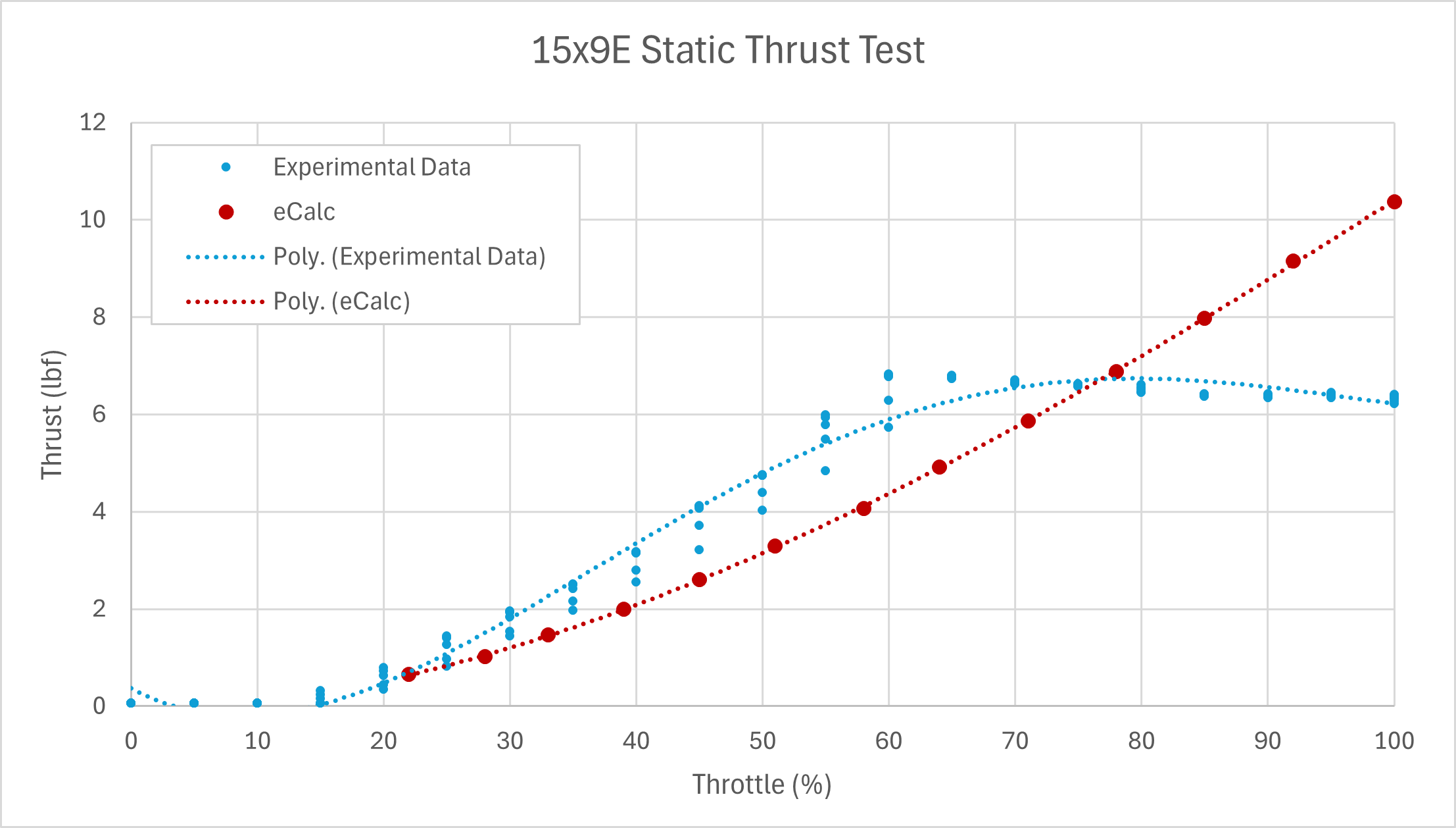
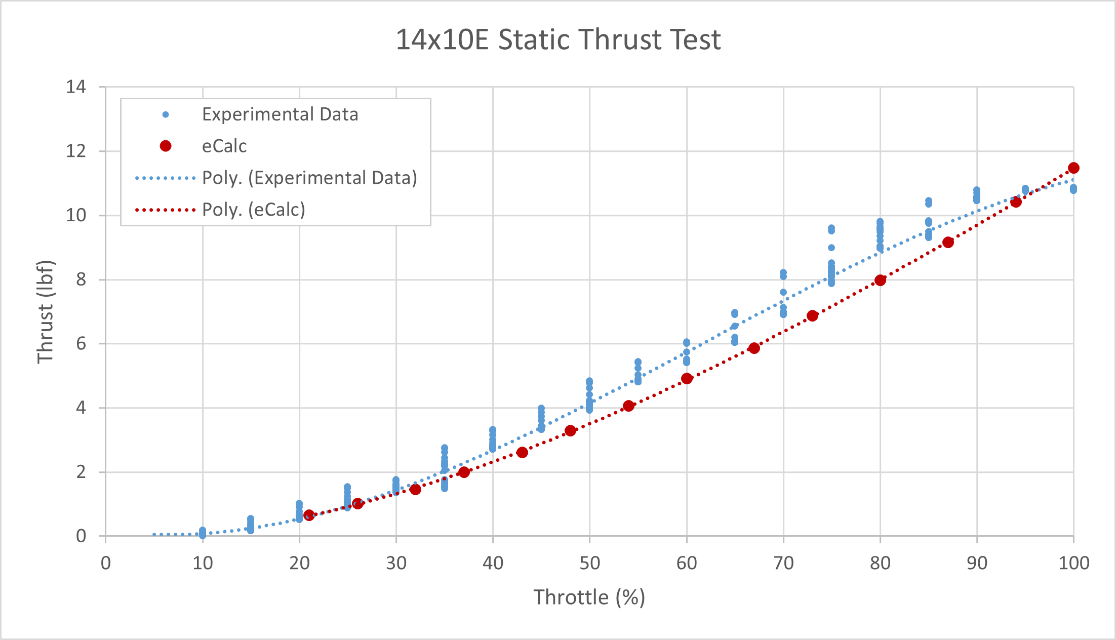
Overall, our data found that the equipment ultimately underperformed our sizing software’s expectations. While this could be due to a flaw in the software, it could also be a mechanical fault in the system. A particular difference in results also occurred at the 80% plateau, where predictions expected a still-increasing thrust.
Rig Construction
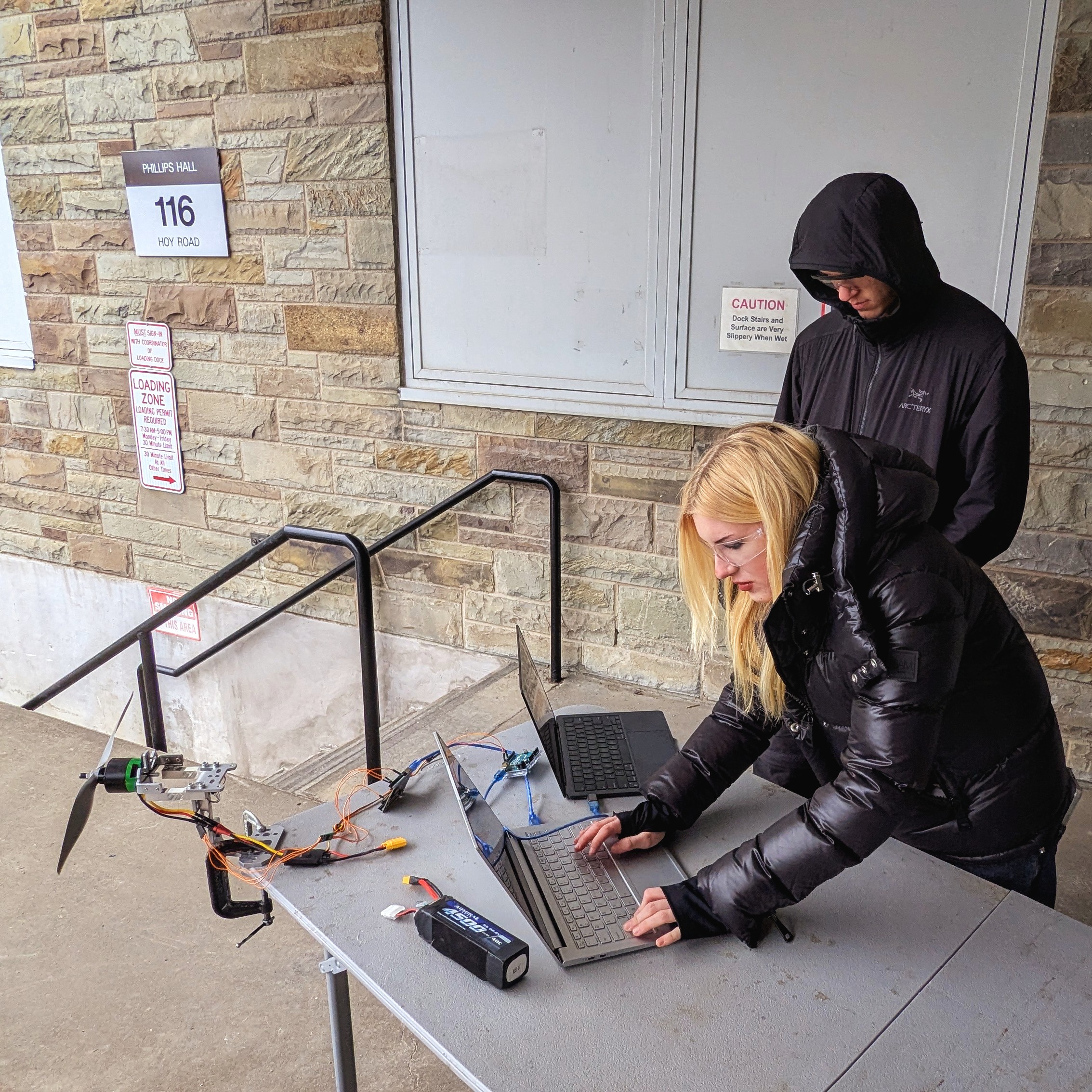
The rig had to be modular, compact, and quick to set up — especially since, for safety, it needed to be run outside with the propeller facing a wall. That meant I couldn’t leave it set up all the time, and quick teardown was essential (particularily in the Ithaca winter).
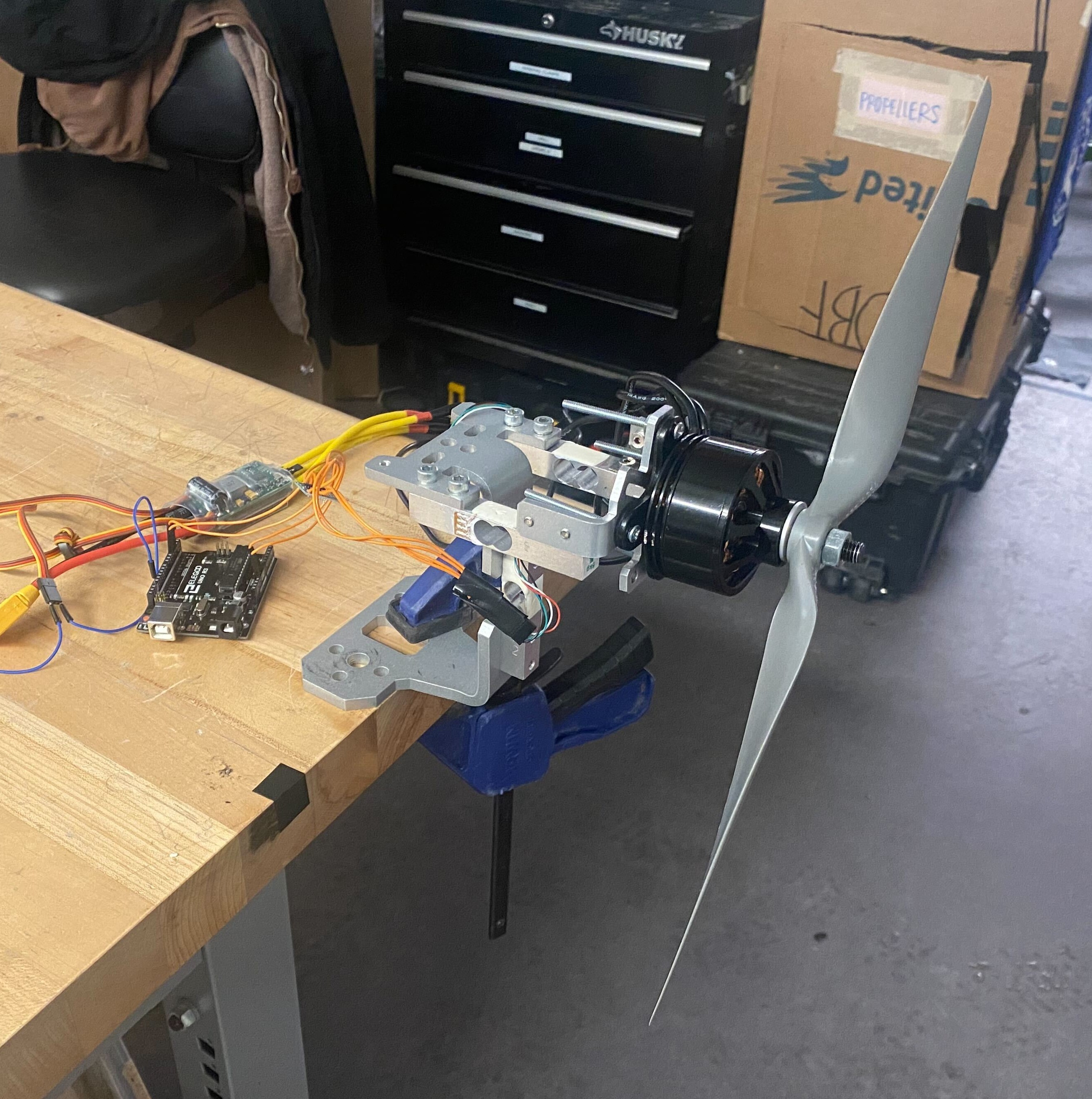
I also designed the rig with the future goal of dynamic testing in mind. That meant it had to be sturdy enough to mount on a moving vehicle for in-motion trials. To handle all this, I settled on a metal base that could be securely clamped to a table or platform, with the electronics housed behind the thrust plane. Load cells were integrated directly into the motor mount structure, ensuring rigid force transmission without play.
Future Development
There’s still a lot of room to improve the rig. Ideally, it would be stand-alone — not needing to be clamped to an external surface. I am also looking to add better mounting for the load cells to completely isolate them from gravitational shear effects. Accordingly, I may return to a modified L-bracket-style testing rig.
More sensors are next on the list: power, current, voltage, and RPM measurements will make the data far more complete and allow better validation of both propeller and electrical models. I am also interested in building out the dynamic testing setup to study propeller performance under better inflow conditions.