Summary
As part of Cornell C-Salt’s effort to design a wave-powered desalination plant, our team needed a reliable way to harness ocean motion and convert it into high-pressure fluid flow — enough to drive seawater through a reverse osmosis membrane. As part of the mechanical subteam, I focused on designing the core wave energy converter (WEC): the mechanism that transforms wave motion into useful work. My goal was to find a design that not only suited the wave environment in Guam but could also be prototyped and tested using the tools and resources we had on hand. Living in Ithaca, Guam, was unfortunately not nearby. After evaluating multiple WEC archetypes, I landed on an oscillating flap system that drove a piston pump, acting as a direct mechanical coupling that eliminated electrical conversion losses and gave us the pressures we needed for filtration.
WEC Design
Early design sessions focused on the wide landscape of wave energy converter types: point absorbers, oscillating water columns, articulated bodies, wave surge devices, and flap-type converters. We looked at the expected wave conditions near the shoreline in Guam and compared those against the operating characteristics of each design. One of the biggest constraints wasn’t just performance, but the manufacturability and deployability at small scale.
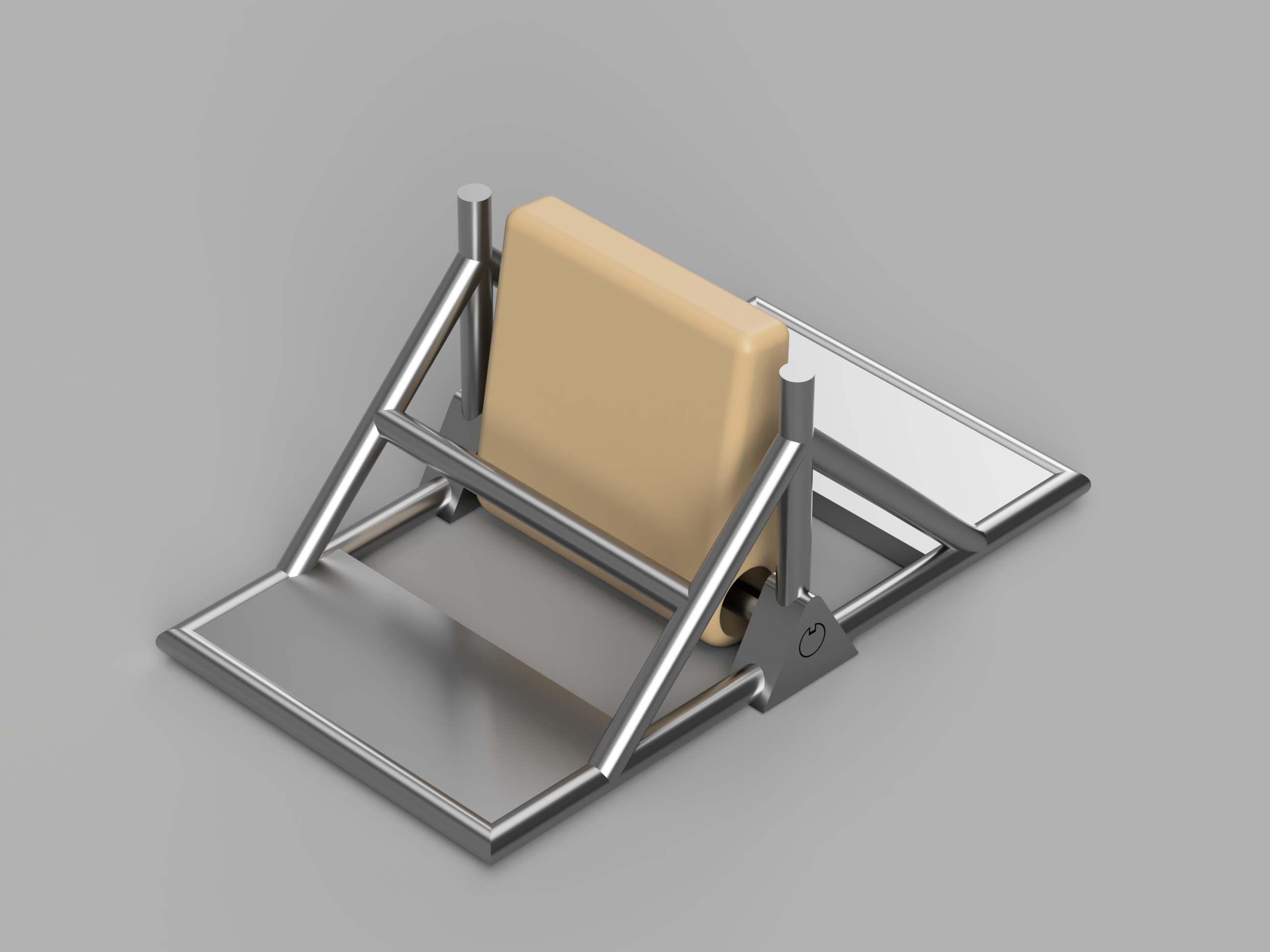
The flap-style WEC stood out. It didn’t require complex buoyancy calculations or precise floating structures. It could be anchored directly to the seabed or mounted in a flume tank, and its geometry was simple enough to model and fabricate. In Guam, the shoreline configuration favored this design too; the flap could be positioned in shallower water on its West coast where surge forces were strong but predictable. By avoiding a floating setup, we reduced the risk of mechanical wear from heaving and simplified the system architecture.
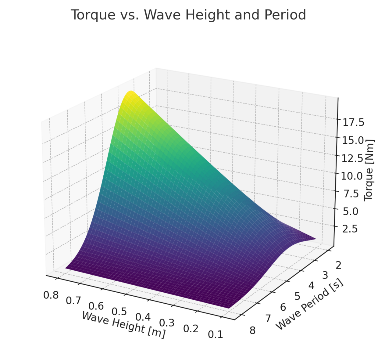
We also ran quick hydrodynamic comparisons between flap geometries to estimate the torque generated across different wave heights and periods. Even without full CFD, the analytical estimates gave us confidence in the flap’s energy capture potential. We built a simple model that combined wave kinematics with projected flap area and lever arm length to estimate the torque acting on the hinge. By sweeping through a range of realistic wave conditions, we generated a surface map of torque output that helped us visualize how the system would perform across different sea states. It wasn’t perfectly precise, but it highlighted trends and gave us a clear sense of where the flap would be most effective.
Water Pressurization
To power desalination, the system needed to push water through a reverse osmosis membrane, which meant generating high pressures, typically around 50–60 bar. We didn’t want to burn efficiency by converting mechanical wave energy into electricity and then back into pressure using pumps. Instead, we opted for a purely mechanical solution: the flap’s motion drove a piston pump directly.
The idea was simple on paper. Each oscillation of the flap rotated a linkage that extended a piston, drawing seawater into a cylinder. On the return stroke, the piston compressed the water and forced it through a check valve network into a pressurization line. That line led to the membrane module.
The major challenge was scaling. Our membrane element was full-size, which meant it needed full-size pressures to operate properly, even in a 1:10 scale prototype. This created a mismatch: small flaps didn’t generate enough energy to reach operational pressures, and large forces exceeded our material limits. We had to either change the membrane, pre-pressurize, or rely on data extrapolation.
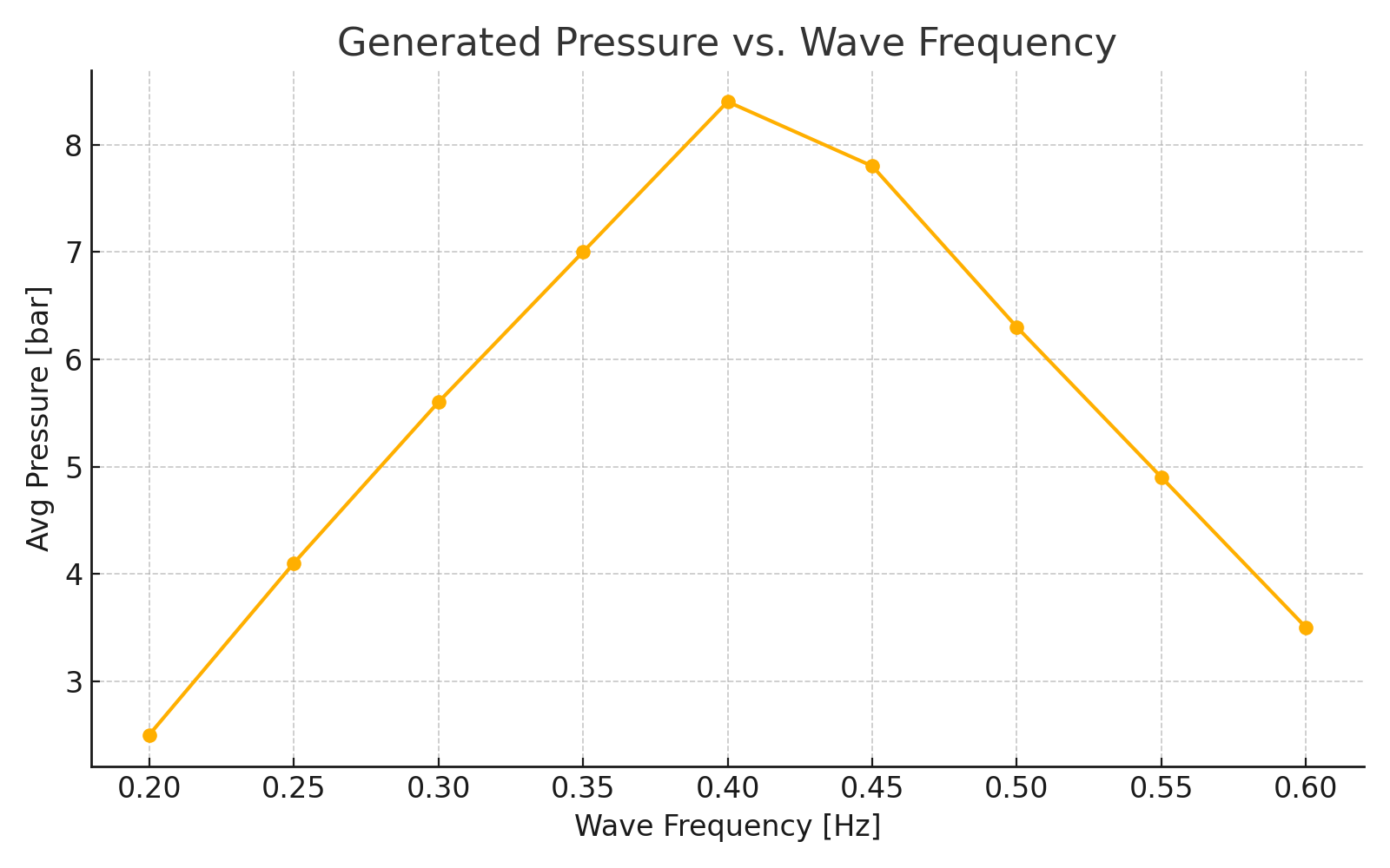
Eventually we compromised by using a scaled-down membrane substitute that mimicked pressure resistance but didn’t require full filtration, just enough to test the force pathway. Modelling the WEC’s flap, we estimated the modified setup could produce a maximum of 8 bar just around 0.4 Hz.
Manufacturing and Testing
Another reason we chose the flap-style WEC was how easily it could be prototyped. The main structure was built from T-slot 80/20 extrusions, which let us rapidly adjust dimensions and mounting points during development. It also meant we could assemble the frame with just an Allen key and a few clamps. No heavy tooling or welding would be required. We used off-the-shelf pillow block bearings and shaft collars for the pivot mechanism, and machined a simple linkage arm to drive the piston. While the 80/20 frame gave us flexibility, it also meant the structure was lighter than a full-scale deployment would be. Since the SeaLab flume didn’t allow us to anchor into the “seafloor,” we added weights to simulate mooring during testing.
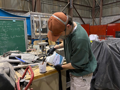
The flap itself was cast from marine-grade rigid foam, chosen for its durability in ocean-like conditions and its ability to approximate the weight distribution of a full-scale flap. We built a mold out of laser-scored acrylic, sealed it with caulk, and reinforced it with a cardboard box to handle the foam’s expansion. Pouring and curing the foam turned out to be more art than science — the material expanded unevenly and didn’t fully coat the bottom of the mold, so we had to cut and sand the result down to size. Still, it was strong, dense, and water-resistant, which was all we needed for a successful first round of testing.
Testing took place in Cornell’s SeaLab flume, where we simulated wave motion using an oscillatory paddle. The flap performed as expected: it oscillated cleanly with the flow, transferred motion to the linkage, and showed measurable pressure increases downstream of the check valves. We ran data acquisition through pressure transducers and displacement sensors to correlate wave input with pressure output.
Peak output pressures reached 8 bar. This result was enough to validate the mechanical path from wave to pressure, even if not quite enough for real desalination. It was a solid first step, and one that gave us real data to build the next iteration on.